
I’m (still) refurbishing a Vandercook 320, and I’ve started attacking the gripper bar. I have it all apart and clean enough to handle, but I have noticed that the studs that hold and adjust the sheet guides seem to be a little off-square.
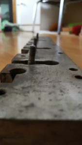
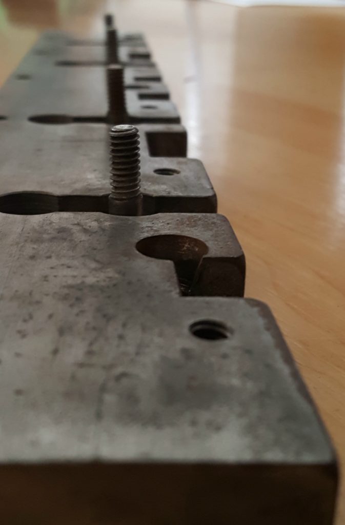
It looks somewhat like the result of crashing the guides (several times), but before I try to straighten them I was wondering if anyone could provide any insight as to whether these might be like this by design.
Even if it is by design, they are not all at the same angle.
My recollection from re-timing my 325 cylinder is that the gripper bar is not at dead top when at rest; rather it is the face of the cylinder that the gripper bar sits against which is positioned at 0 degrees or 12 o’clock, so the gripper bar is slightly forward.
This method only works on the presses which use a pivoting frame to raise and lower the impression drum. Newer presses like the SP series rotate an eccentric carrier for the drum bearings so the only choice is to roll the carriage off the end of the bed or remove a section of the racks.
I didn’t know that. Thanks, Kevin. Very happy to learn something new.
This may only be applicable to the 320/325 series. Certainly not the SP and Universal series or the Nos. 3 and 4, 15-21 … I will investigate.
On the 320 you can also remove the LR-23 pins that the NN-68 cylinder bearing blocks pivot on for the trip/print position, then use a lever to raise the drum to clear the racks. No heavy lifting required, but you have to make sure you slack off the CB-11 shoe and its setscrew before trying to remove the pins.
In any case I don’t have the feedboard for my press so the only reference I have is to match the leading edge of the drum’s impression surface with the start of the bed’s printing area.
You may only be off by one or two teeth. For the benefit of other 320 owners, I’ll describe how to retime the impression cylinder.
Timing or indexing means choosing which tooth on the cylinder will contact the end tooth on the cylinder rack (track) so that the gripper heads are parallel to the feed board. (The side of the tooth may have been marked, but that often is not the case.) Mistimed cylinders cause the grippers to bend paper and gripper heads may smash type high material in the bed.
To commence:
– Obtain an engine hoist *
– Conscript two strong friends as spotters
– Roll the carriage forward 3/4 of the way down the bed
– align hoist at the end of the press
– attach ratchet straps to the carriage and hoist, cinch enough to support but not lift the carriage
– Remove the bumper blocks
– Roll the carriage forward until the cylinder gears clear the racks
– Rotate the cylinder as needed in the stationary carriage
– Push the carriage back onto the racks until the gears engage with the racks, shift carriage laterally if needed
– Return carriage to feed board
– Repeat as needed until the timing is correct
*This is required because of the weight of the carriage. Also, the cylinder racks (tracks) are a single piece on each side, which means that the cylinder can only be rotated in the carriage once the cylinder gears clear the racks near the end of the bed. A forklift set level with the bed bearers can be substituted.
Other models, e.g. the No. 4, later Universals, and later SP20 have sectional racks that can be removed to allow retiming in the middle of the bed.
And I don’t know why I keep calling it a 325 when it is a 320! I’m going to correct the original post to avoid confusing posterity.
Paul, thanks for the info. I suspect that I can straighten them sufficiently by bending them back into proper position. They aren’t bent enough that this will weaken them, and being exactly perpendicular is not critical to their function anyway.
I was wondering about the gripper bar position at the feedboard. I knew the end of the feedboard was angled and I expected the gripper bar to park a little clockwise of 12 o’clock to match that angle. Yet I just got my drum timing set so the leading edge of the impression surface of the drum comes down directly over the head line marked on the bed (and also the edge of the head bar), and the gripper bar seems to park at exactly 12 o’clock. I must admit that I don’t necessarily have the carriage stops at that end adjusted properly, but they would have to be moved quite a bit to change the angle of the gripper bar by much. The manual doesn’t show the timing of the impression cylinder, and I don’t have a feedboard to match it up with…
These studs are bent. The manual Sheet No. 52 shows that the studs are perpendicular to the body of the gripper bar.
The front end of the feed board is at an angle. The gripper bar is 90° to the feed board end.
Studs are swedged into the gripper bar from the backside. A machinist could install new studs. NA Graphics may have replacements (LR-76). I think that they are the same part as the stud for No. 4 (CR-266). The latter is 2″ long and the threaded end is 1/4-28.