I’m fixing up a filthy Vandercook 320 press, and I’ve just been cleaning up the carrier mechanism for the form rollers.
I stripped everything off the carriage including the LN-19 Ink Frame Brackets (one on each side). The parts have been cleaned and now it’s time to reassemble things.
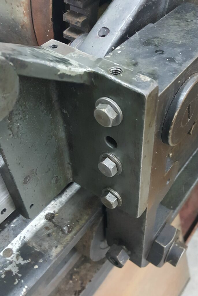
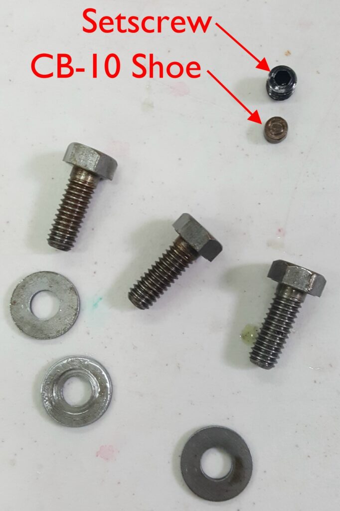
Reattaching the LN-19’s leaves me with a bit of a mystery, though. These are each held to the carriage with three bolts, but there is also a screw hole in the top of the bracket which takes a setscrew and a CB-10 Shoe. The latter is a small brass disk which allows the setscrew to press against the top mounting bolt, thus giving fine adjustment to the height of the bracket, without marring either the bolt or the setscrew.


Because the disk is so thin it only provides about 0.1″ of adjustment.
It isn’t clear to me why this adjustment exists, or how it should be set. All I can see is for it to ensure that the inboard ends of the LS-67 Ink Frame Supports don’t foul with either the LR-48 Tie Rod or the fulcrum ends of the NN-68 Cylinder Bearings. I would have thought the LN-19 brackets could have been made with a ledge that sat on the top surface of the side frames to keep everything positioned properly, but perhaps Vandercook decided this was a point of excessive accumulation of manufacturing tolerances so it needed some adjustability?
So does anyone have any thoughts on how to adjust this? The actual form roller height adjustment is the usual 3-bolt arrangement in the cradle.

I would expect the factory to have some sort of jig to hold the part in the correct position for installation while the bolts are tightened. Having something like this setscrew mechanism also makes little sense for allowing future removal and installation in the field. It is too easy to take apart, or put out of adjustment, during disassembly. Furthermore, the reference surface is the side of a bolt, which is hardly a precision surface. They would have installed taper pins if the positioning were critical on re-installation.
I also notice that the bracket has an extra hole not occupied by a bolt. At first I though this might be a clue that the same part in used in several presses but now I realize this hole provides access to another setscrew and shoe which retain the LR-23 Pins that the cylinder bearings rotate on during the trip/print transition. This would allow removal of the cylinder without removing the ink frame brackets.
My hunch is that this relates to the initial factory assembly and is not an intended point of later adjustment.
DGM