
I recently had to remove both trip springs from my SP-15. I approached each one differently, so I’ll explain both methods.
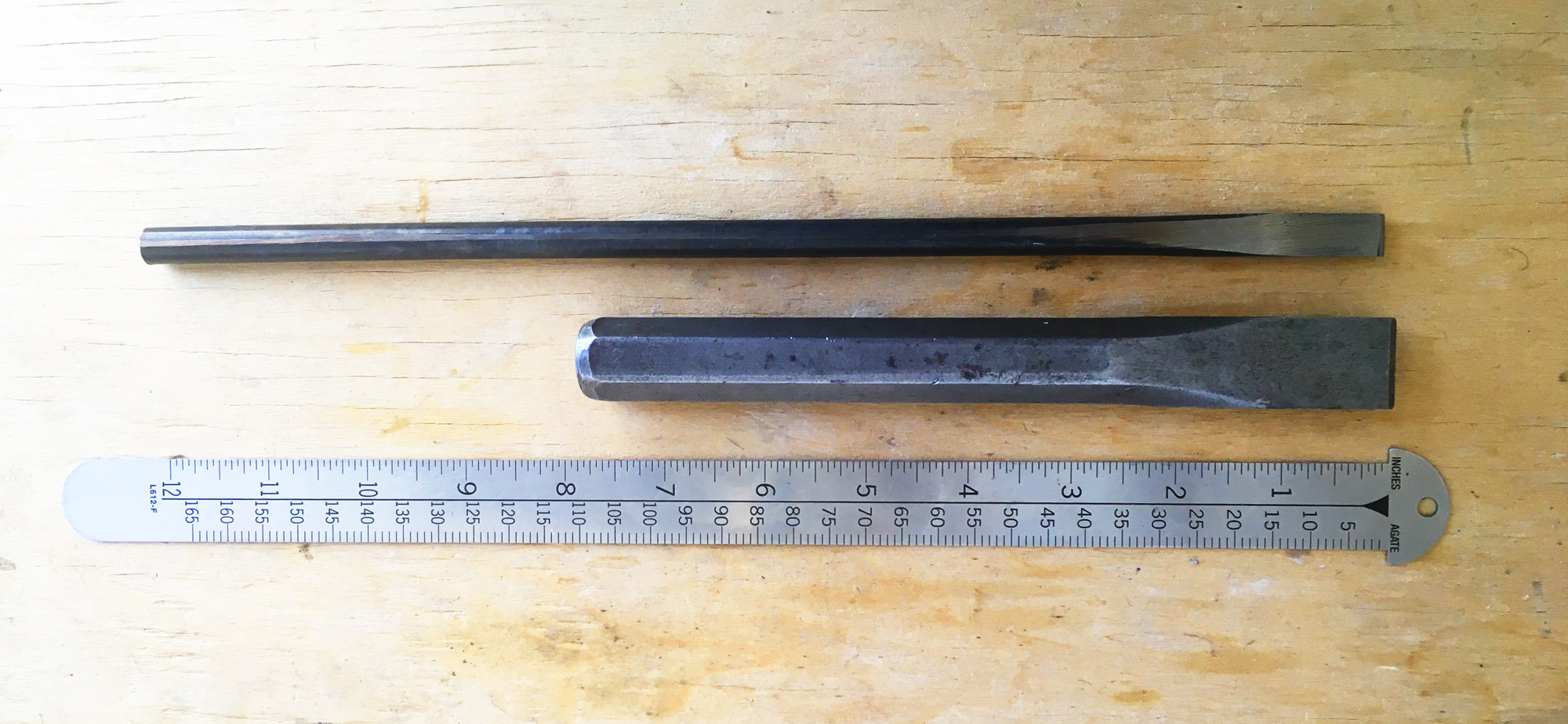
The discovery that not just one but both springs were broken came a couple months ago, but it took some time to procure the right tools for removing the old springs, namely a cold chisel and the 3 lb. hammer appropriate to the task (following the instructions on Sheet 302, an addendum to the SP manuals). I also tried in vain to locate anyone who had purportedly performed this same operation on an SP.
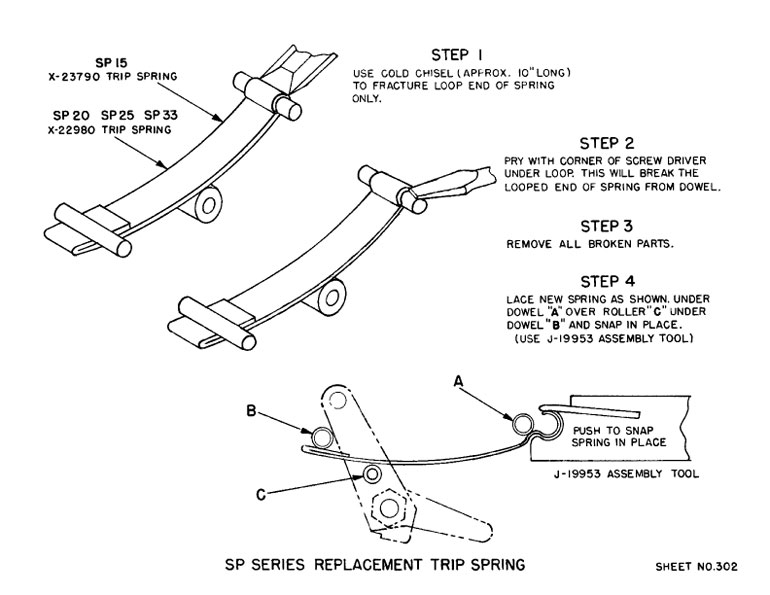
The longest cold chisel I found was just shy of eight inches, with a blade about 7/8″ wide — very nearly as wide as the gap it needs to operate within. Chisels of a more suitable width were too short to reach the target while also protruding enough to get any grip on. I enlisted the help of a friend who is well versed at hammering on metal, and before coming over, he fashioned a cold chisel with a 3/8-inch blade and a 12-inch stock — something that may not exist in the wild. The added length meant it can be gripped around its midpoint—ideal for holding it steady while readying a hammer blow—while the blade rests against the target, a full five inches inside the carriage.
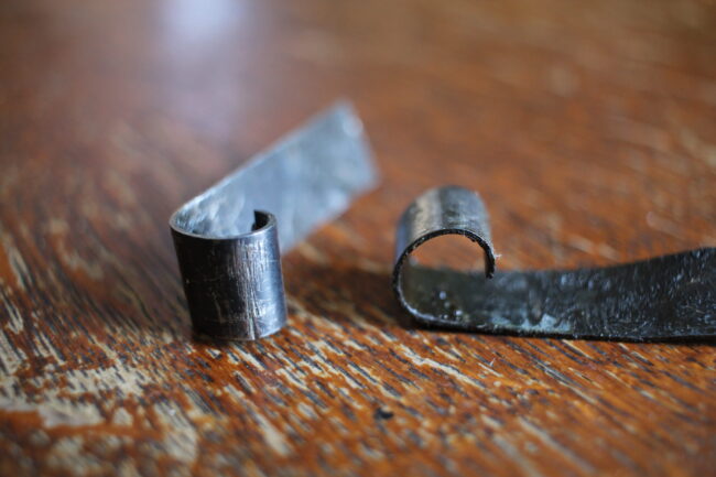
We followed the instructions for the fracturing of the spring, but ultimately the spring didn’t fracture: the repeated hammering on the spring loop caused it slowly to open (See Fig. 2). After about an hour of careful blows (not by me, but by the seasoned metalworker) the loop had widened enough that we could wrench the spring off its post.
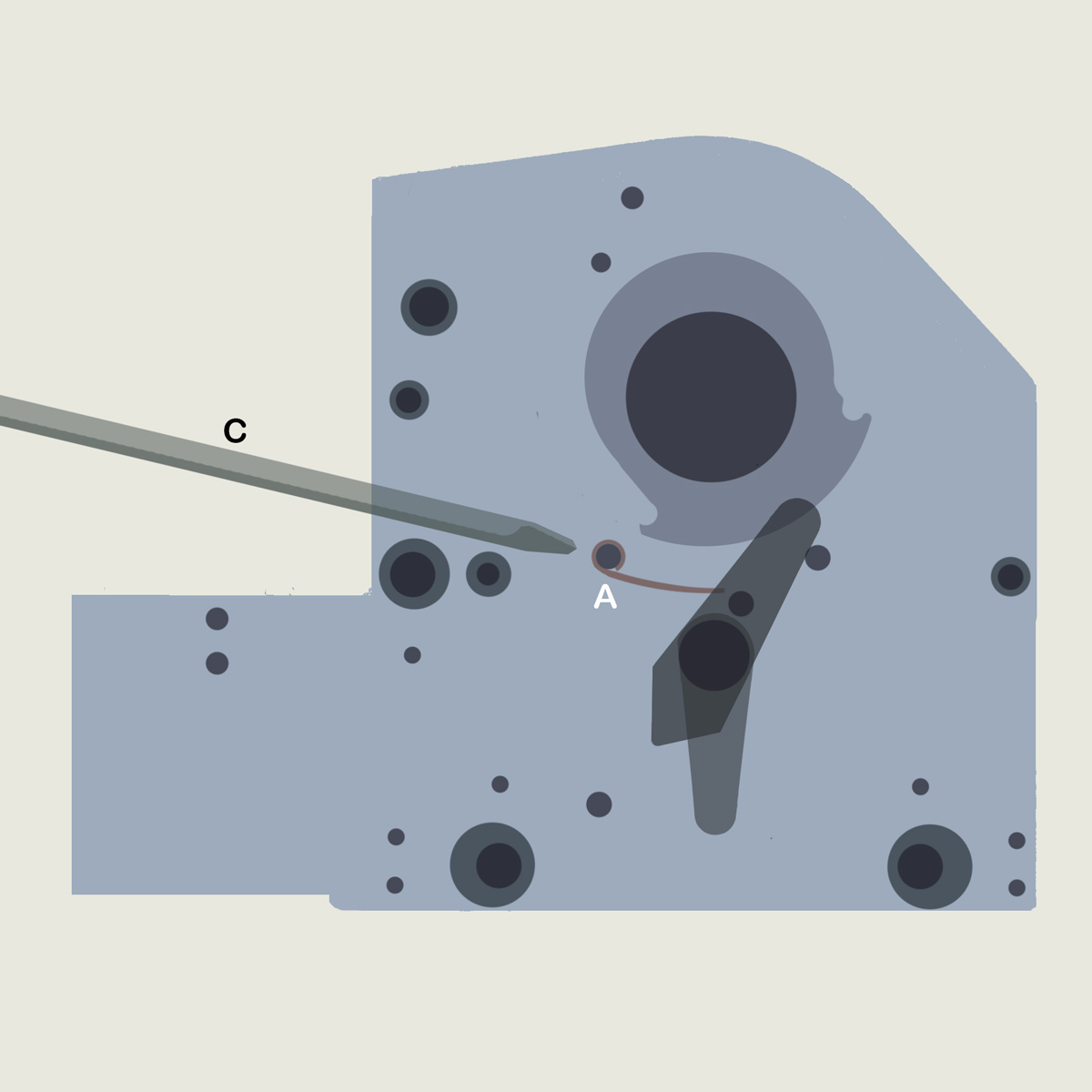
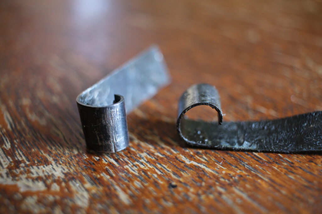
It was only after we’d removed the spring that we could see its anatomy clearly (see Fig. 4). I hadn’t understood that the old spring is in fact an open loop. Knowing this, I approached the second one differently. With the second spring, instead of aiming to fracture it, I flipped it upward to expose the cleft (see Fig. 3), and, inserting a shim to brace the spring in place, pointed the chisel directly into the cleft. It took only a few substantial blows to distend the spring enough to wrest it loose with pliers. (and this time it was my own, inexpert hammering) I highly recommend this second approach if you can maneuver the spring into the appropriate position. It was both faster and felt far less risky.
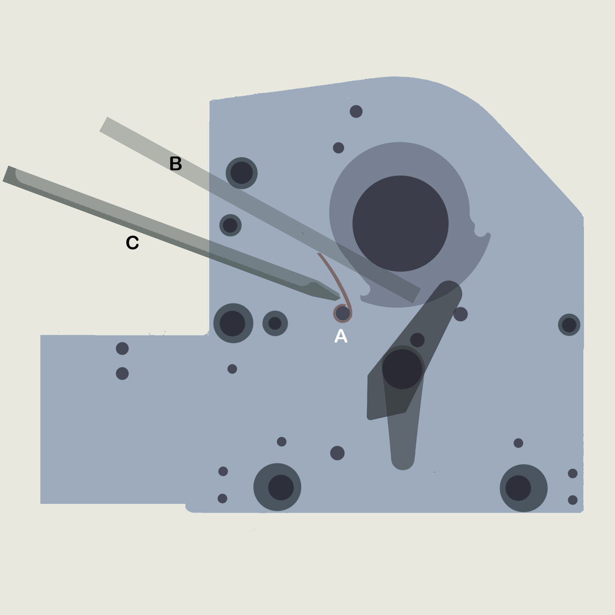
Sheet 287-A in the SP15 manual shows the loop-end of the trip spring at the front of the carriage. The spring will perform as designed regardless of direction.
Conversely, Sheets 297–298 in the SP20 manual shows the looped-end of the the trip spring at the rear of the carriage.
Ok Paul, i will try, thank you so much for the guidance! I still have one question: yesterday I noticed that regarding the trip springs, the one on the operator side is loose and underneath the pin at the front, and at the back, it is wrapping around the pin. On the opposite side, the positioning is reversed—it is loose at the back and wrapping around the pin at the front. I’m completely confused as to which side is correct. In the image you sent, it seems like it stays loose from the front pin (pin A) and wraps around the rear pin (pin B). Is that correct?
The attached illustration from Sheet 302 shows the trip spring on the dowels and the trip arm position in Print mode. Think of the trip arm as a clock, with the lower arm pointing to 4 o’clock.
You should be able to strike the out-of-alignment arm with a wood block and a hammer to shift it to match the opposite side.
If you can knock the looped end of the trip spring back onto the dowel, enlist another person to use a screwdriver to ensure the folded end is under the other dowel.
There should be four white plastic trip rollers (X-21119): the rear pair shifts the impression cylinder into print, and the front pair shifts the cylinder into trip at the end of forward carriage travel.
The rear studs for the trip rollers are eccentric. Check that the both sides match.
Oil the eccentrics and the notch at the top of the side on the carriage side plates.
Just more one
More one
More one pic
Hello everyone, good morning!The carriage of my Vandercook SP15 is jamming about 10 cm (4 inches) after leaving the feed board. Since it has been sitting idle for a long time, I had to free up the actuator pins which were seized. Even after doing that, the carriage is still jamming.I removed the feed board to get a better view and noticed a difference between the trip springs on each side. Looking at your article, I am confused about which side has the correct positioning.On the operator side: This metal piece (the rear trip spring) sits on top of a fixed pin. It looks engaged, but at the front of the carriage, it does not wrap around the fixed pin.On the opposite side (gear side): The piece seems to have slid backward, visually covering the fixed pin. Meanwhile, at the front of the carriage, this piece is wrapping around the fixed pin.I am not sure which side is correct, whether any of them are broken, or if I can just readjust them to unjam the carriage. Any help would be greatly appreciated!
No, I don’t endorse the “fracture” method, unless the loop is closed and can’t be pried open. Prying requires less force and is less likely to damage the dowel.
Paul, to clarify: would you not endorse the “fracture” method, then? I’d gotten that instruction from your 2007 post here: SP20 Trip Spring Repaired.
Thank you for sharing your procedure. I’ve generally recommend using a long screwdriver and 3 lb. hammer to pop off the looped end from the inside so as to not skew or damage the dowel. However, in this case, the loop is essentially closed and therefore the best approach. It was the first leaf spring design Vandercook used. Later it was modified with a gap in the loop and a bend underneath for the jaw of the install tool. To install closed loop springs, one would need to cut a section of the loop or remove the side plate.