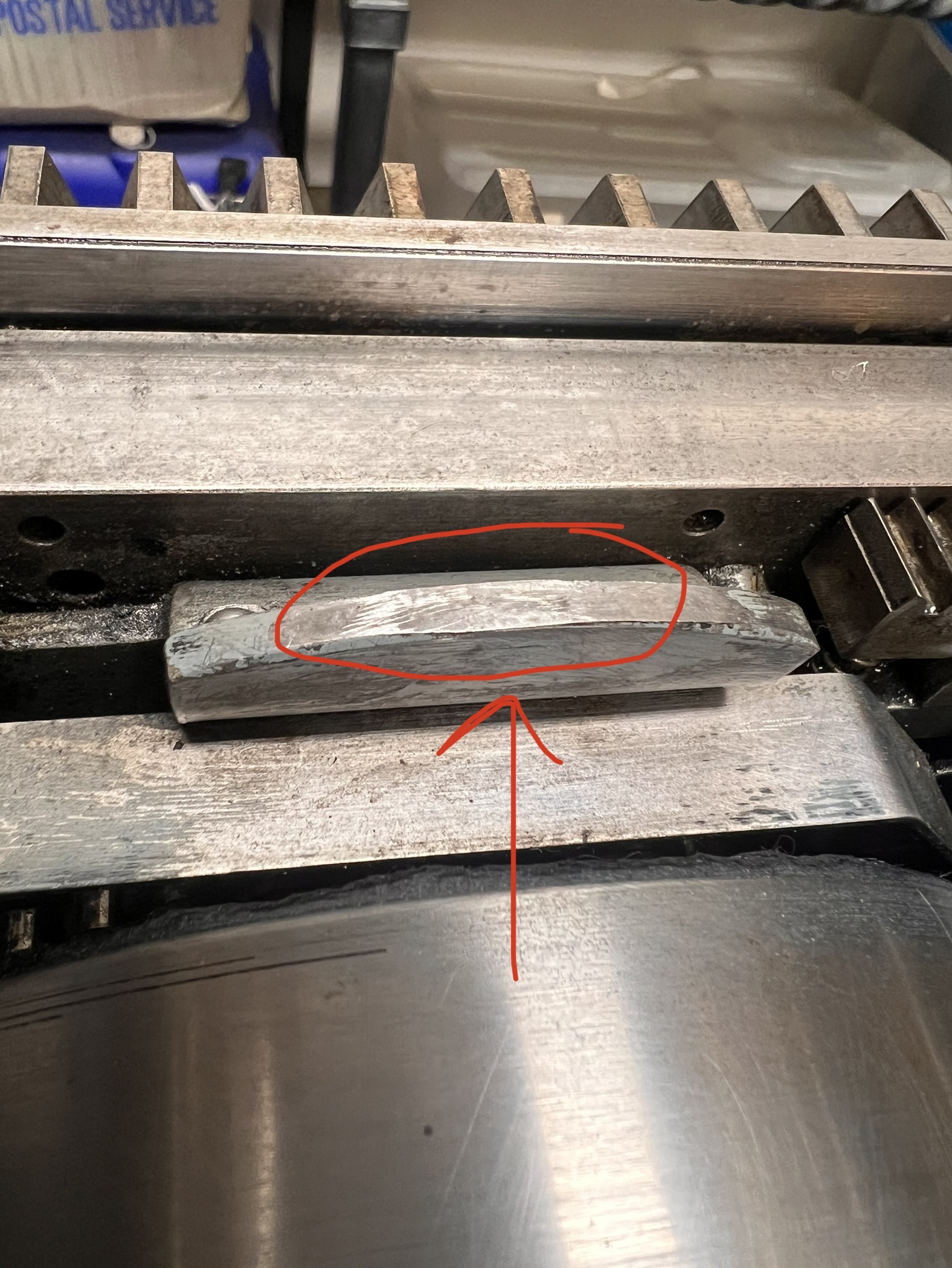
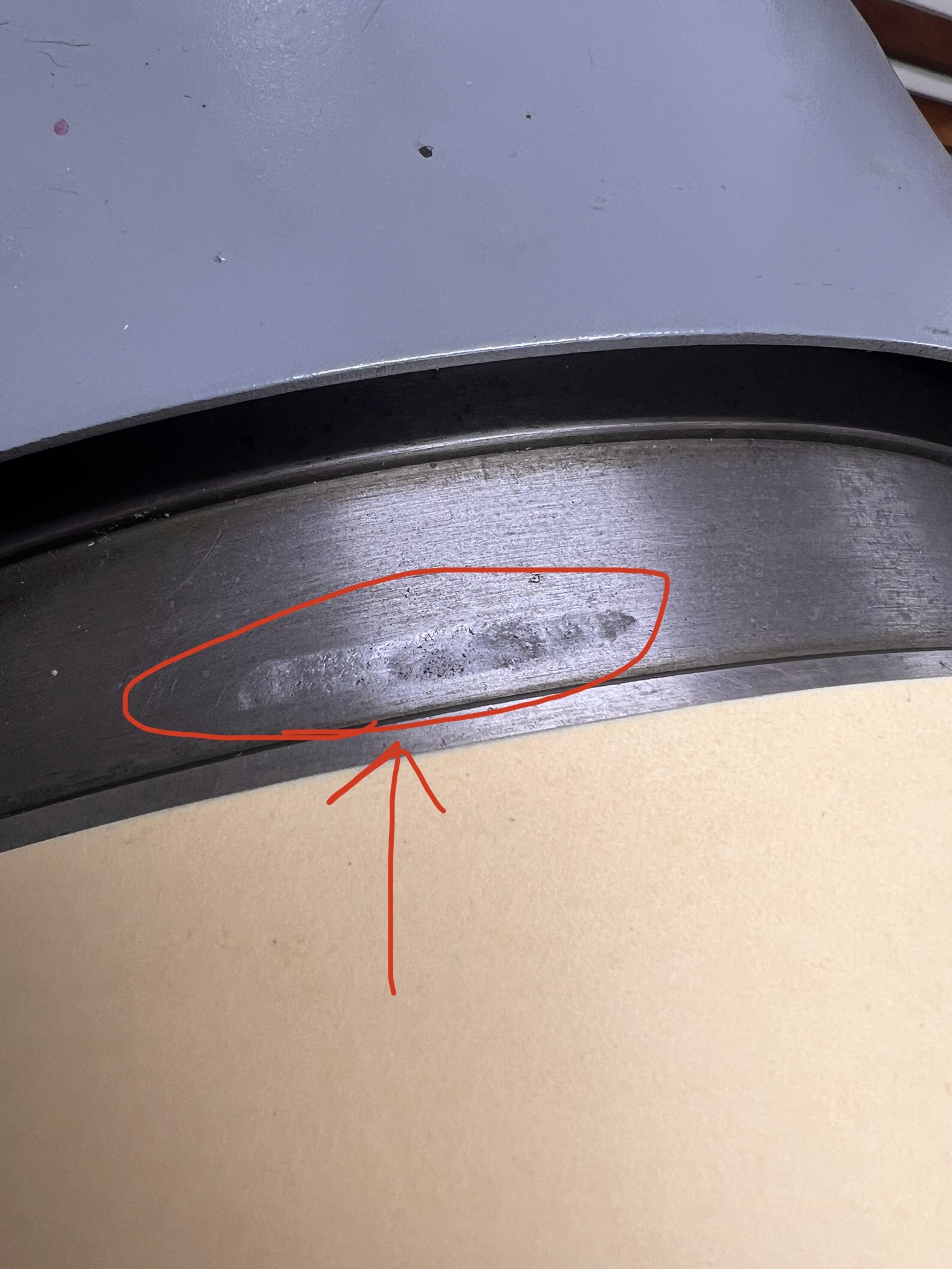
I noticed that the drum cam (especially on the non-operator side) is looking worn. There’s corresponding wear on the cylinder. Does this indicate I need to adjust the screws on the support arms per page 11 in Paul’s book? If so, I’m a little unclear what screws I should be adjusting.
thank you!


There shouldn’t be any significant resistance in getting past this tab so I think you are right in being concerned. Now that everything is together and moving, you might want to revisit your eccentric adjustments.
Thank you Dan and Paul! You’re right Dan, it’s not on a critical part of the cylinder. My bigger concern, which likely got lost in that long post was, maybe I’m causing some uneven wear to the whole press and that blemish was an indicator. Also, the cylinder is very difficult to progress down the press bed when the tension is so high on the ink drum cam. I’m fairly strong and it takes considerable effort. I’m going to recheck the impression for evenness…since I did put the press back together and it’s possible that’s off.
This is not on the working face and not on the cylinder bearer, but in the space between them. It seems a bit crazy, but I think this is just what these do. Does anyone have an SP-20 that doesn’t have an impact blemish in this spot?
DGM
I wonder if it might be better to patch the wear on the cylinder, then reshape the cam and shim it up.
This advice was helpful. However I seem to of course have cascading issues. Bear with me as this is a long post.
When I adjusted the ink drum cam to hit the cylinder less hard the ink drum no longer made contact with the geared form roller. So, I adjusted for the lightest contact possible and checked that the ink drum was level as confirmed by a spirit level. (I had already checked that the form rollers were level to the form and press bed with a lollipop gauge.)
However, when inked up, only the operator side showed signs of ink transference between the form roller and the ink drum. I continued to adjust the non operator side ink drum until it too made contact as evidenced by ink distribution. Unfortunately, it’s back to hitting the cylinder harder than I would like when in trip.
Next thing I noticed is that in order for the form rollers to be level to the press bed, the non operator side adjusting knobs are both significantly higher than the operator side.This might explain why I have to raise the ink drum on that side so much. I did check the diameter of the form rollers and they are ~3.005″ on both ends and brand new.
So my next working theory was that the form roller supports might have some discrepancies. One is original and one was recently fabricated. I’m not sure how much of a difference is statistically significant between the two. I checked the diameter of the nylon rollers on each side and there is a difference of about .004″ which doesn’t seem to account for the difference in roller knob adjustment. I also checked some other components that I thought might effect the roller adjusment, but couldn’t find anything significantly different between the two. To be fair, my digital caliper is mediocre, not professional machinist worthy.
I have also noted that, the form gear doesn’t make contact with the gear rack. Although, I don’t currently have in any of the shims in, so I might need to put those back in. But it still doesn’t explain why the form rollers need such different adjustment on one side of the press vs. the other.
So my next thought is, are my impression bearings possibly misadjusted? Could the impression bearings possibly be raising the whole cylinder higher on the non-operator side and that’s really the root of my problem? I have tested the impression previously and thought the impression appeared balanced right to left. But I could check again.
If the impression is balanced which I think it is, I’m stumped about what is causing the rollers to need greater adjustment on the non-operator side vs. the operators side.
I should note that for anyone other than Paul commenting since he knows this, my SP20 came to me heavily disassembled and I’ve spent about two years working on getting it put back together and into to a working state.
Loosen horizontal set screw “A” and then turn height screw “B” clockwise to lower and counterclockwise to raise.